


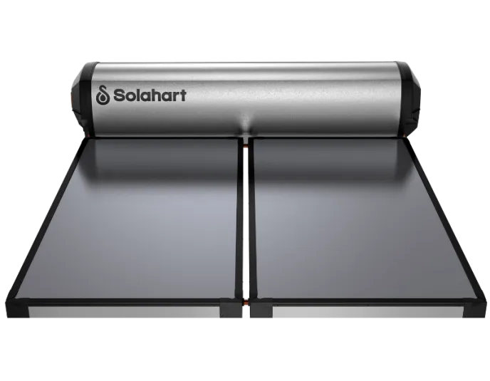
Solahart 302LCSD
The Solahart 302LCSD offers reliable, energy-efficient solar water heating for medium-sized households. Its open-circuit thermosiphon system and corrosion-resistant features make it ideal for a variety of Australian climates.
Solahart 302LCSD Solar Water Heater: Key Attributes
Why the 302LCSD system is a smart choice
The Solahart 302LCSD is designed for medium-sized households of 6 or more people, providing a 302L tank to meet the daily hot water needs of your family. This system uses open circuit thermosiphon technology to efficiently harness solar energy with minimal maintenance. Its TRV valve ensures safe operation, and the Super Shield Enamel protects the tank from corrosion, making it suitable for different climates, including areas with moderate water conditions. The LCSD Series offers significant energy savings, helping reduce water heating costs by up to 80%.
Key Features:
- Capacity: 300-Litre tank, ideal for medium households (6 or more people).
- Open Circuit Thermosiphon: Efficient solar heating system with low maintenance.
- TRV Valve: Provides safe pressure relief for smooth system operation.
- Super Shield Enamel: Corrosion-resistant coating for longer-lasting durability.
- Energy Efficient: Save up to 70% on water heating costs.#
- Reduced CO2 Emissions: Save up to 2.8 tonnes of CO2 annually.#
Warranty:
- 10-year warranty on the collector and tank.*
- 5-year warranty on parts and labour.*
Collectors:
- 2 x LCSD Collectors - for higher efficiency for use in low to medium solar gain areas.
-
Specifications

Model - 300 tank Tank Model - LCSC Series 300L Tank Model - LCSC Free Heat 300LF Storage Capacity (litres) 300 Boost Capacity (litres) 150 Weight Empty (kg) 91 Weight Full (kg) 391 A-Width* (m) 2.43 Model - 302 system Tank Model - LCSC Series 300L Tank Model - LCSC Free Heat 300LF Storage Capacity (litres) 300 Boost Capacity (litres) 150 Weight Empty (kg) 160 Weight Full (kg) 464 A-Width* (m) 2.48 LCS Collector Aperture (Heating) Area (m2) 1.87 Dimensions - Length (mm) 1943 Dimensions - Width (mm) 1027 Dimensions - Height (mm) 83 Capacity (litres) 1.9 Weight - Empty (kg) 31 Weight - Full (kg) 33 Working Pressure 1000 Absorber Surface Mirotherm sputtered selective surface Absorber Material Aluminium Riser Material Copper Number of Risers 6 Tray Material 0.7mm aluminium Insulation Material - Base 38mm glasswool blanket Insulation Material - Sides Polyester blanket Glass 3.2mm tempered low iron Water Supply TPR Valve Setting (kPa) 1000 ECV* Setting (kPa) 850 Max. Supply Pressure - With ECV (kPa) 680 Max. Supply Pressure - Without ECV (kPa) 800 Water Connections - Cold DN15 compression fitting Water Connections - Hot R 1/2 Supply Voltage 220 V - 250 V Electric Boost Specifications Heating Unit Type Copper sheath immersion element -
How it works
How Roof Top Solar Systems Work
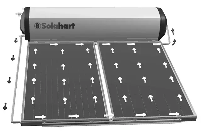
Solar Operation
The 302LCSD solar system has its vitreous enamel lined solar storage tank installed on the roof directly coupled to the solar collectors. It works on the simple scientific fact that hot water rises. As the sun heats the water in the solar collectors, the increase in temperature causes the water to rise through an insulated copper pipe into the storage tank. This allows cooler water from the solar storage tank to flow into the solar collectors to be heated by the sun‟s energy. This process continues while solar energy is available.
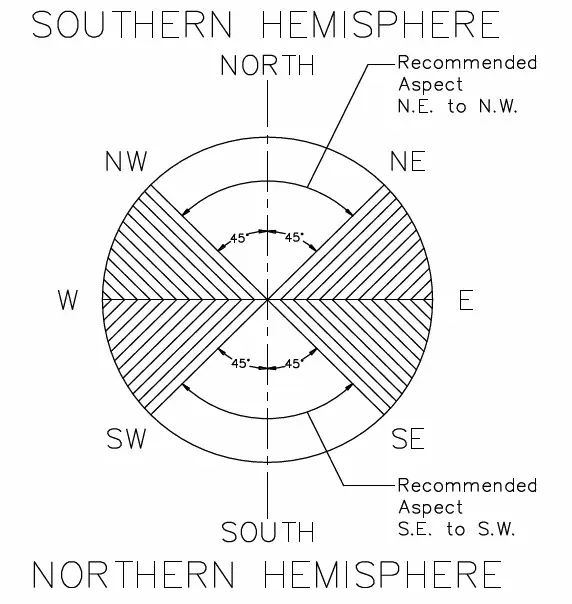
Orientation of Solar Collectors
To help maximise system performance, solar collectors should be installed with an optimum orientation facing true north (in the southern hemisphere) or true south (in the northern hemisphere). Always check for true north or true south using a compass or other suitable device.
To help maximise system performance, solar collectors should be installed with an optimum inclination. This is equal to 90% to 100% of the local latitude angle when collectors are oriented within 60° of true north or true south, and between 10° and 20° if the collectors are oriented between 60° and 90° from the optimum orientation. Generally, improved summer performance is obtained from an angle of inclination less than the optimum angle and improved winter performance is obtained by an angle of inclination greater than the optimum angle. If the angle of inclination varies by 20° from the optimum angle, the solar collectors will receive about 10% less total annual solar radiation.
Frost/Freeze Protection
An Open Circuit system does not have freeze protection and is not suitable for installation in areas prone to freeze conditions. Freeze conditions occur below 5°C (41°F). This system has NO WARRANTY for freeze damage. In areas that are prone to frost / freezing, a Closed Circuit system should be used.
Solar Boosting
In-Tank Boosting
An isolating switch is installed in the electrical meter box for an electrically in-tank boosted model. This should be left switched on to allow the booster heating unit to operate if required. The booster heating unit is for heating the water at times of low solar energy gain, such as during very cloudy or rainy weather, or during the colder months. The booster heating unit will only activate if heating is required and power is available from the switchboard. When the water is below the thermostat setting, the booster heating unit will turn on and heat the water. The booster heating unit will automatically turn off when the temperature of the water reaches the thermostat setting. If the water temperature drops below the setting again the booster will re-activate.
In-Series Gas Boosting
An in-series gas booster (also known as a continuous flow gas booster) can be installed between the solar water heater and the hot outlets in the house. This booster should be permanently active. The booster senses the temperature of the water passing through it: if the water temperature is above its temperature setting it does nothing; if below it will automatically heat the water up to the preset outlet temperature setting. This gas booster ensures hot water delivery for a variety of hot water demands without the need for user intervention while enabling maximum solar energy contribution to the water heating. For more information on this booster, consult the owner’s manual for the product.

Over-Temperature Protection System
The 302LCSD Open Circuit Series system has a ‘TRV’ thermosiphon restrictor valve located between the cold inlet of the tank and the cold inlet of the collectors. This valve restricts the flow through the collectors when the tank has reached a sufficiently high temperature.